The oscilloscope screen capture shows the PWM output on the bench with a mark to space ratio set at 1:1 and RC=10ms. Where it should be at half the supply at 2.428V [lower right reading ripple left over from smooting on theĪrduino analog output is large at 253mV (top blue line). Warning: For these values 10k, 1uF smoothing may not be enough.

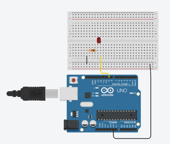
Smoothly fading LED output (in reality the light is pulsing on and off). LED and current limit resistor to a PWM pin. All that matters is the amount of current fed The inductance and resistance filter the PWM signal

PWM signals are often used to drive motors (a large inductance with Have to be filtered out and the easiest way is to create a low passįilter formed from a resistance and a capacitance. There are several ways to smooth a PWM signal: The following diagram shows the difference in average voltage for low, middle and high M:S ratios: Simple way of generating a continuously varying output voltage using voltage to create the Arduino analog output. The output which can be smoothed into a steady D.C. Varying the Mark to Space (M:S) ratio alters the average voltage at Writes them once and they keep generating the PWM signal allowing your Hardware modules attached to the timers to automatically output theĬhosen M:S ratio without further programming. Really useful thing about these outputs is that they use internal If you need a fairly good voltage then the PWM outputs are very useful.įor the standard Arduino Uno there are six analog output pins you can use. So if you are looking for absolute accuracy you should use aĭedicated DAC that does have a complete set of resistive dividers insideĮ.g. Is involved there will be some feed through of the fundamental frequency PWM signal is separated from the next starting edge by the same period). The PWM signal is repeated at a constant frequency (the start of each In the waveformĪbove you can see the M:S ratio changing as the sine wave is generated. Mark to space ratio within the digital output signal.

Is that the latter is created using varying The difference between a true analog output voltage and a PWM voltage Instead it uses aĭigital PWM signal that can be smoothed to create an average voltage, The sense that the microcontroller does not have a resistive divider toĬreate the voltage (The exception is the Arduino Due).

Observe the real effect of different smoothing capacitors resistor pairs.Īrduino Analog Output pins do not generate a true analog output in See real life PWM results measured on my bench using an oscilliscope.Find out the Speed Capabilities of PWM e.g.Why one PWM output pair uses a H igher Frequency clock compared to the other 4.Find out what Internal Modules are needed to Implement PWM.Find out why there are only 6 PWM outputs.The secret is PWM (Pulse Width Modulation) and averaging.
#Arduino arduino analogwrite implementation how to
How to create Analog Output using only digital pins with analogWrite.How to generate an Analog Output varying from 0V to 5V using onlyĭigital pins! It sounds impossible as digital pins output only 5V or 0V. Arduino Analog Output Arduino Analog Output:Impossible Analog using Digital Pins.


 0 kommentar(er)
